Isuzu Rodeo UE. Service manual — part 341
6E2–119
RODEO 6VD1 3.2L ENGINE DRIVEABILITY AND EMISSIONS
Diagnostic Trouble Code (DTC) P0101 MAF System Performance
D06RW057
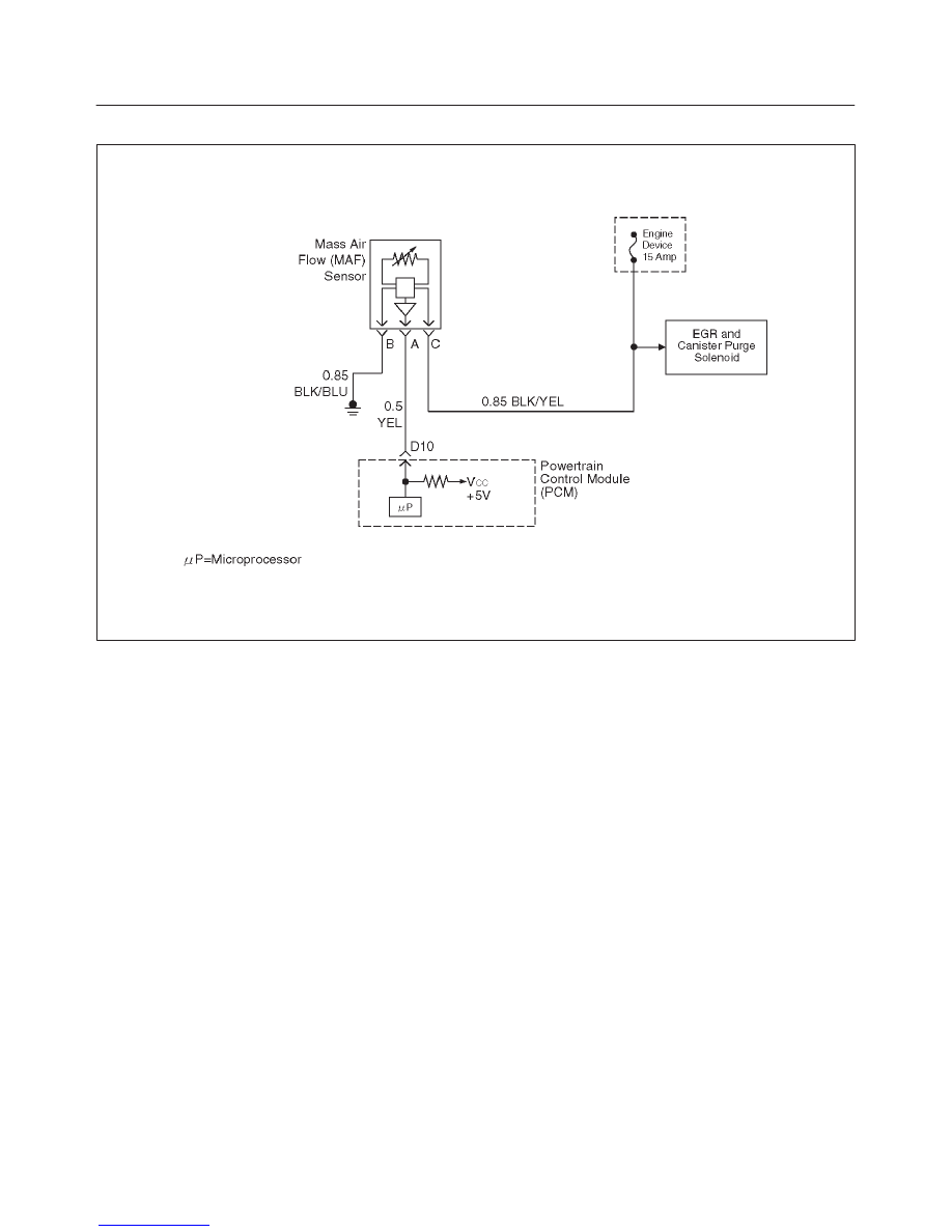
Circuit Description
The mass air flow (MAF) sensor measures the amount of
air which passes through it into the engine during a given
time. The powertrain control module (PCM) uses the
mass air flow information to monitor engine operating
conditions for fuel delivery calculations. A large quantity
of air entering the engine indicates an acceleration or high
load situation, while a small quantity or air indicates
deceleration or idle.
The MAF sensor produces a frequency signal which can
be monitored using a Tech 2. The frequency will vary
within a range of around 4 to 7 g/s at idle to around 25 to 40
g/s at maximum engine load. DTC P0101 will be set if the
signal from the MAF sensor does not match a predicted
value based on throttle position and engine RPM.
Conditions for Setting the DTC
f
The engine is running.
f
No TP sensor or MAP sensor DTCs are set.
f
The throttle is steady, TP angle doesn’t change by
more than 1%.
f
System voltage is between 11.5 volts and 16 volts.
f
Calculated air flow is between 25 g/second and 40
g/second.
f
Above conditions present for at least 1 second.
f
MAF signal frequency indicates an airflow significantly
higher or lower than a predicted value based on throttle
position and engine RPM for a total of 12.5 seconds
over a 25-second period of time.
Action Taken When the DTC Sets
f
The PCM will illuminate the malfunction indicator lamp
(MIL) after the second consecutive trip in which the
fault is detected.
f
The PCM calculates an airflow value based on idle air
control valve position, throttle position, RPM and
barometric pressure.
f
The PCM will store conditions which were present
when the DTC was set as Freeze Frame and in the
Failure Records data.
Conditions for Clearing the MIL/DTC
f
The PCM will turn the MIL “OFF” on the third
consecutive trip cycle during which the diagnostic has
been run and the fault condition is no longer present.
f
A history DTC P0101 will clear after 40 consecutive
warm-up cycles have occurred without a fault.
f
DTC P0101 can be cleared by using the Tech 2 “Clear
Info” function or by disconnecting the PCM battery
feed.
Diagnostic Aids
An intermittent may be caused by the following:
f
Poor connections.
f
Mis-routed harness.
f
Rubbed through wire insulation.
f
Broken wire inside the insulation.
Refer to Intermittents under service category Symptoms.
Any un-metered air may cause this DTC to set. Check for
the following:

6E2–120
RODEO 6VD1 3.2L ENGINE DRIVEABILITY AND EMISSIONS
f
The duct work at the MAF sensor for leaks.
f
An engine vacuum leak.
f
The PCV system for vacuum leaks.
f
An incorrect PCV valve.
f
The engine oil dip stick not fully seated.
f
The engine oil fill cap loose or missing.
Test Description
Number(s) below refer to the step number(s) on the
Diagnostic Chart.
2. The MAF system performance or “rationality”
diagnostic uses the MAP sensor signal along with
other input to calculate an expected airflow rate that
is then compared to the actual measured airflow
from the MAF sensor. The first few steps of this
table verify that the MAP sensor is working properly.
6. Verifies the signal circuit from the MAF sensor
electrical connector to the PCM.
Verifies whether a ground and B+ circuit is
available.
DTC P0101 – MAF System Performance
Step
Action
Value(s)
Yes
No
1
Was the “On-Board Diagnostic (OBD) System Check”
performed?
—
Go to
Step 2
Go to
OBD
System
Check
2
1. Ignition “OFF.”
2. Disconnect the Mass Air Flow (MAF) Sensor
harness connector from the MAF Sensor.
3. Place an unpowered test lamp between the 12 volt
signal circuit and the ground circuit, both at the MAF
Sensor connector.
4. Ignition “ON,” Engine“OFF.”
Did the test lamp illuminate?
—
Go to
Step 6
Go to
Step 3
3
1. Ignition “ON,” Engine “OFF.”
2. Using a Digital Voltmeter (DVM), check the 12 volt
signal circuit for the correct voltage.
Did the DVM indicate a value within the following
range?
11.5 to 12.5
Volt
Go to
Step 5
Go to
Step 4
4
1. Ignition “OFF.”
2. Check the 12 volt signal circuit for the following
conditions:
f
An open circuit
f
A short to ground
Was the problem found?
—
Verify repair
—
5
Check the MAF ground circuit for the following
conditions:
f
An open circuit
f
A short to voltage
Was a problem found?
—
Verify repair
—
6
1. Ignition “OFF.”
2. Check the MAF Sensor signal circuit between the
PCM and the MAF Sensor for the following
conditions:
f
An open circuit
f
A short to ground
f
A short to battery voltage
Was a problem found?
—
Verify repair
Go to
Step 7

6E2–121
RODEO 6VD1 3.2L ENGINE DRIVEABILITY AND EMISSIONS
DTC P0101 – MAF System Performance
(Cont'd)
Step
No
Yes
Value(s)
Action
7
1. Connect the MAF Sensor wiring harness connector
to the MAF Sensor.
2. Connect the Tech 2 to the vehicle.
3. Place the Transmission in Park/Neutral, and fully
apply the Parking Brake.
4. Start the engine.
5. Select the Mass Air Flow (MAF) parameter on the
Tech 2.
With the engine idling, does the Tech 2 display the
following value(s)?
4 to 7 g/s
Go to
Step 8
Go to
Step 9
8
Observe the Tech 2 value while increasing the engine
RPM to its upper limit.
Does the Tech 2 display the following value(s)?
25 to 40 g/s
Go to
Step 10
Go to
Step 9
9
Replace the MAF Sensor.
Is the action complete?
—
Verify repair
—
10
Replace the PCM.
IMPORTANT: The PCM must be reprogrammed. Refer
to PCM reprogramming.
And also refer to latest service bulletin.
Check to see if the Latest software is released or not.
And then Down Load the LATEST PROGRAMMED
SOFTWARE to the replacement PCM.
Is the action complete?
—
Verify repair
—
6E2–122
RODEO 6VD1 3.2L ENGINE DRIVEABILITY AND EMISSIONS
Diagnostic Trouble Code (DTC) P0102 MAF Sensor Circuit Low Frequency
D06RW057
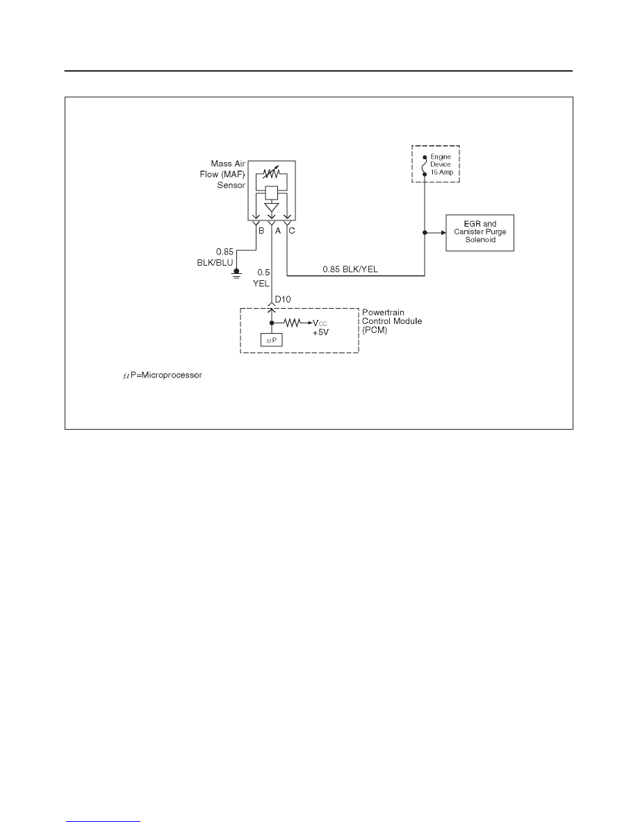
Circuit Description
The mass air flow (MAF) sensor measures the amount of
air which passes through it into the engine during a given
time. The powertrain control module (PCM) uses the
mass air flow information to monitor engine operating
conditions for fuel delivery calculations. A large quantity
of air entering the engine indicates an acceleration or high
load situation, while a small quantity of air indicates
deceleration or idle.
The MAF sensor produces a frequency signal which can
be monitored using a Tech 2. The frequency will vary
within a range of around 4 to 7 g/s at idle to around 1900
Hz at maximum engine load. DTC P0102 will be set if the
signal from the MAF sensor is below the possible range of
a normally operating MAF sensor.
Conditions for Setting the DTC
f
The engine is running above 500 RPM for greater than
10 seconds.
f
System voltage is above 11.5 volts.
f
MAF signal frequency is below 1.6 g/s for a total of
50-percent of the last 1000 samples monitored. A
sample is taken every cylinder event.
Action Taken When the DTC Sets
f
The PCM will illuminate the malfunction indicator lamp
(MIL) the first time the fault is detected.
f
The PCM calculates an air flow value based on idle air
control valve position, throttle position, RPM and
barometric pressure.
f
The PCM will store conditions which were present
when the DTC was set as Freeze Frame and in the
Failure Records data.
Conditions for Clearing the MIL/DTC
f
The PCM will turn the MIL “OFF” on the third
consecutive trip cycle during which the diagnostic has
been run and the fault condition is no longer present.
f
A history DTC P0102 will clear after 40 consecutive
warm-up cycles have occurred without a fault.
f
DTC P0102 can be cleared by using the Tech 2 “Clear
Info” function or by disconnecting the PCM battery
feed.
Diagnostic Aids
Check for the following conditions:
f
Poor connection at PCM – Inspect harness connectors
for backed-out terminals, improper mating, broken
locks, improperly formed or damaged terminals, and
poor terminal-to-wire connection.
f
Misrouted harness – Inspect the MAF sensor harness
to ensure that it is not routed too close to high voltage
wires.
f
Damaged harness – Inspect the wiring harness for
damage. If the harness appears to be OK, observe the
Tech 2 while moving connectors and wiring harnesses
related to the MAF sensor. A change in the display will
indicate the location of the fault.
f
Plugged intake air duct or filter element – A wide-open
throttle acceleration from a stop should cause the
mass air flow displayed on a Tech 2 to increase from
Нет комментариевНе стесняйтесь поделиться с нами вашим ценным мнением.
Текст