Jeep Commander (2010 year). Manual — part 10
WARNING!
To avoid serious injury or death:
• Do not use a three-prong adaptor.
• Do not insert any objects into the receptacles.
• Do not touch with wet hands.
• Close the lid when not in use.
• If this outlet is mishandled it may cause an electric
shock and failure.
CUPHOLDERS
Front Cupholders
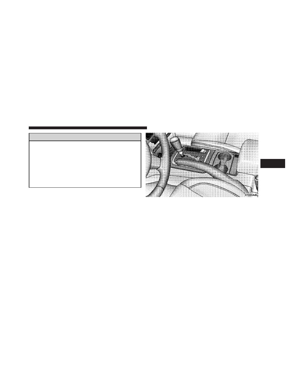
There are two cupholders for the front seat passengers,
located in the center console.
Front Cupholders
3
UNDERSTANDING THE FEATURES OF YOUR VEHICLE
145
Cupholders — Second Row Seat
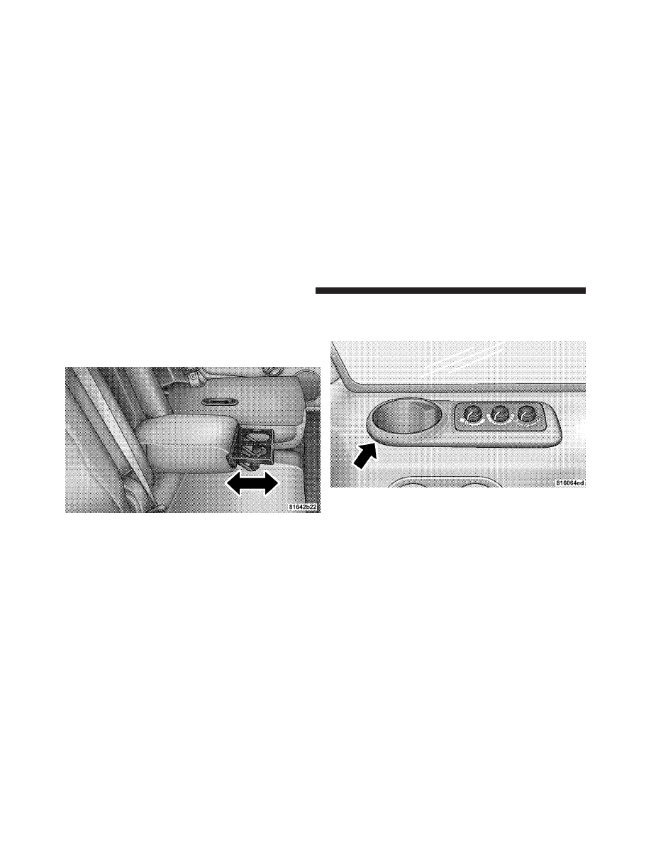
The second row seat has two cupholders in the center
armrest. Lower the center armrest. Refer to “Seats” in this
section. Press the front of the cupholder, and the cup-
holder will come out of the armrest.
Cupholders — Third Row Seat
The third row seat passengers have cupholders on the left
and right rear trim panels.
Cupholders — Second Row Seat
Cupholders — Third Row Seat
146
UNDERSTANDING THE FEATURES OF YOUR VEHICLE
CARGO AREA FEATURES
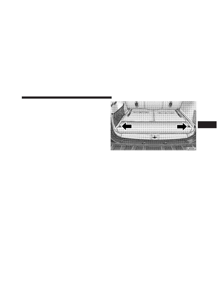
Cargo Load Floor
The panel in the load floor is reversible for added utility.
One side is carpeted and the other side features a plastic
lined tray which holds a variety of items.
The cargo load floor is held by spring loaded latches. In
order to use the cargo load floor, use the following
procedure:
NOTE:
The cargo load floor latches should not be
used as cargo tie-downs.
Rear Storage Cover
3
UNDERSTANDING THE FEATURES OF YOUR VEHICLE
147
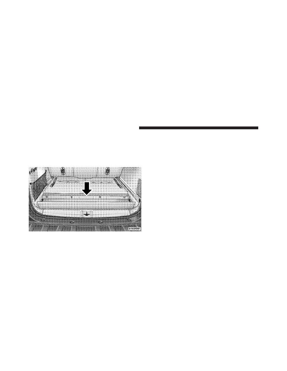
1. Flip up pull loop(s) so they are perpendicular (straight
up) to the top surface of the tray.
2. Pull up on loop(s) and twist 90 degrees, so they are
parallel to the slotted hole in tray.
3. Lift tray over loop(s), and reposition tray.
4. Pull up on loop(s) and twist 90 degrees, so they are
perpendicular (straight up) to the slotted hole in tray.
5. Push loop(s) back down, so they are parallel to the top
of the tray.
REAR WINDOW FEATURES
Rear Window Wiper/Washer
The rear wiper/washer is controlled by a rotary switch
located on the control lever. The control lever is located
on the right side of the steering column.
Cargo Load Floor
148
UNDERSTANDING THE FEATURES OF YOUR VEHICLE
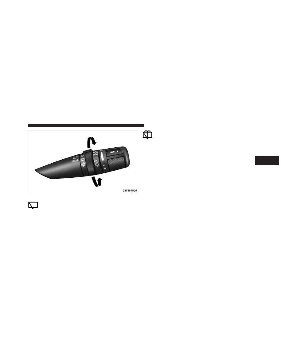
Rotate the switch upward to the “On” position to
activate the rear wiper.
NOTE:
The rear wiper operates in an intermittent mode
only.
Rotate the switch upward to the “washer” position
to activate that rear washer. The washer pump will
continue to operate as long as the lever or ring is
engaged. Upon release, the wipers will cycle two times
before returning to the set position.
If the rear wiper is operating when the ignition is turned
OFF, the wiper will automatically return to the “park”
position if power accessory delay is active. Power acces-
sory delay can be cancelled by opening the door; if this
happens, the rear wiper will stop at its current position
and will not go to “park”.
If the liftgate flipper glass is open, connection to the rear
window wiper is interrupted preventing activation of the
rear wiper blade. When the liftgate flipper glass is closed,
the rear wiper switch, or the ignition switch, needs to be
turned OFF and ON to restart the rear wiper.
Rear Wiper/Washer Control
3
UNDERSTANDING THE FEATURES OF YOUR VEHICLE
149
Rear Window Defroster
The rear window defroster button is located on the
climate control panel. Press this button to turn on
the rear window defroster and the heated outside mirrors
(if equipped). An indicator in the button will illuminate
when the rear window defroster is on. The rear window
defroster automatically turns off after approximately
10 minutes. For an additional five minutes of operation,
press the button a second time.
NOTE:
To prevent excessive battery drain, use the rear
window defroster only when the engine is operating.
CAUTION!
Failure to follow these cautions can cause damage to
the heating elements:
(Continued)
CAUTION! (Continued)
• Use care when washing the inside of the rear
window. Do not use abrasive window cleaners on
the interior surface of the window. Use a soft cloth
and a mild washing solution, wiping parallel to
the heating elements. Labels can be peeled off
after soaking with warm water.
• Do not use scrapers, sharp instruments, or abra-
sive window cleaners on the interior surface of the
window.
• Keep all objects a safe distance from the window.
ROOF LUGGAGE RACK — IF EQUIPPED
The crossbars and siderails are designed to carry the
weight on vehicles equipped with a luggage rack. The
load must not exceed 150 lbs (68 kg), and should be
uniformly distributed over the luggage rack crossbars.
150
UNDERSTANDING THE FEATURES OF YOUR VEHICLE
NOTE:
If not equipped with crossbars, your authorized
dealer can order and install MOPAR
威 crossbars built
specifically for this roof rack system.
Distribute cargo weight evenly on the roof rack crossbars.
The roof rack does not increase the total load carrying
capacity of the vehicle. Be sure the total load of cargo
inside the vehicle plus that on the external rack does not
exceed the maximum vehicle load capacity.
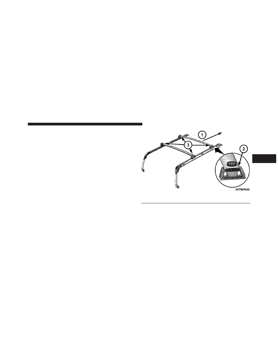
The optional crossbars must be installed using the correct
orientation (the longer crossbar toward the front) with
the raised edge (wind trip) toward the front of the
vehicle.
1 — Front of Vehicle
3 — Thumb Screws
2 — Raised Edge (Wind Trip)
3
UNDERSTANDING THE FEATURES OF YOUR VEHICLE
151
The optional crossbars must also be secured in one of the
five detent positions marked with an arrow on the
siderails to prevent movement. To move the crossbars,
loosen the thumb screws located at the upper edge of
each crossbar approximately eight turns, then move the
crossbar to the desired position, keeping the crossbars
parallel to the rack frame. Once the crossbar is in one of
the five detent positions, retighten the thumb screws to
lock the crossbar into position.
NOTE:
• To help control wind noise when the crossbars are not
in use, place the front crossbar in the first detent from
the front of the vehicle and the rear crossbar in the
second detent from the rear of the vehicle.
• If the rear crossbar (or any metallic object) is placed
over the satellite radio antenna (if equipped), you may
experience interruption of satellite radio reception. For
improved satellite radio reception, place the rear cross-
bar in the second detent from the rear of the vehicle
when not in use.
• The grab handles on the back of the vehicle (if
equipped) are not to be used as a towing feature.
CAUTION!
• To prevent damage to the roof of your vehicle, DO
NOT carry any loads on the roof rack without
crossbars installed. The load should be secured
and placed on top of the crossbars, not directly on
the roof. If it is necessary to place the load on the
roof, place a blanket or some other protection
between the load and the roof surface.
(Continued)
152
UNDERSTANDING THE FEATURES OF YOUR VEHICLE
CAUTION! (Continued)
• To avoid damage to the roof rack and vehicle, do
not exceed the maximum roof rack load capacity of
150 lbs (68 kg). Always distribute heavy loads as
evenly as possible and secure the load appropri-
ately.
• Long loads which extend over the windshield,
such as wood panels or surfboards, or loads with
large frontal area should be secured to both the
front and rear of the vehicle.
• Travel at reduced speeds and turn corners care-
fully when carrying large or heavy loads on the
roof rack. Wind forces, due to natural causes or
nearby truck traffic, can add sudden upward lift to
a load. This is especially true on large flat loads
and may result in damage to the cargo or your
vehicle.
WARNING!
Cargo must be securely tied before driving your
vehicle. Improperly secured loads can fly off the
vehicle, particularly at high speeds, resulting in per-
sonal injury or property damage. Follow the roof rack
cautions when carrying cargo on your roof rack.
3
UNDERSTANDING THE FEATURES OF YOUR VEHICLE
153
UNDERSTANDING YOUR INSTRUMENT PANEL
CONTENTS
䡵 Instrument Panel Features . . . . . . . . . . . . . . . 158
䡵 Instrument Cluster . . . . . . . . . . . . . . . . . . . . 159
䡵 Instrument Cluster Description . . . . . . . . . . . . 160
䡵 Electronic Vehicle Information Center (EVIC) . . 170
▫ Electronic Vehicle Information Center (EVIC)
Displays . . . . . . . . . . . . . . . . . . . . . . . . . . . 172
▫ Engine Oil Change Indicator System . . . . . . . 175
▫ Trip Functions . . . . . . . . . . . . . . . . . . . . . . 176
▫ Compass Display . . . . . . . . . . . . . . . . . . . . 179
▫ Personal Settings (Customer-Programmable
Features) . . . . . . . . . . . . . . . . . . . . . . . . . . 181
▫ System Status . . . . . . . . . . . . . . . . . . . . . . . 185
䡵 Sales Code (RER/REN) — AM/FM/CD/DVD
Radio – If Equipped . . . . . . . . . . . . . . . . . . . . 186
▫ Operating Instructions — Voice Recognition
System (VR) — If Equipped . . . . . . . . . . . . . 186
▫ Operating Instructions — uconnect™ phone
— If Equipped . . . . . . . . . . . . . . . . . . . . . . 186
▫ Clock Setting Procedure . . . . . . . . . . . . . . . 186
4
䡵 Sales Code RES — AM/FM Stereo Radio With
CD Player (MP3 AUX Jack) . . . . . . . . . . . . . . . 189
▫ Operating Instructions — Radio Mode . . . . . 189
▫ Operation Instructions — CD Mode For CD
And MP3 Audio Play . . . . . . . . . . . . . . . . . 192
▫ Notes On Playing MP3 Files . . . . . . . . . . . . 194
▫ Operation Instructions - Auxiliary Mode . . . . 197
䡵 Sales Code RES/RSC — AM/FM Stereo Radio
With CD Player (MP3 AUX Jack) And Sirius
Radio. . . . . . . . . . . . . . . . . . . . . . . . . . . . . . . 197
▫ Operating Instructions — Radio Mode . . . . . 198
▫ Operation Instructions — CD Mode For CD
And MP3 Audio Play . . . . . . . . . . . . . . . . . 203
▫ Notes On Playing MP3 Files . . . . . . . . . . . . 205
▫ List Button (CD Mode For MP3 Play) . . . . . . 208
▫ Info Button (CD Mode For MP3 Play) . . . . . . 208
䡵 Universal Consumer Interface (UCI)
— If Equipped . . . . . . . . . . . . . . . . . . . . . . . . 209
▫ Connecting The iPod威 . . . . . . . . . . . . . . . . . 210
▫ Using This Feature . . . . . . . . . . . . . . . . . . . 211
▫ Controlling The iPod威 Using Radio
Buttons . . . . . . . . . . . . . . . . . . . . . . . . . . . 211
▫ Play Mode . . . . . . . . . . . . . . . . . . . . . . . . . 211
▫ List Or Browse Mode . . . . . . . . . . . . . . . . . 213
䡵 uconnect™ studios (Satellite Radio) — If
Equipped (REN/RER/RES Radios Only). . . . . . 215
▫ System Activation . . . . . . . . . . . . . . . . . . . . 215
▫ Electronic Serial Number/Sirius
Identification Number (ESN/SID) . . . . . . . . . 215
156
UNDERSTANDING YOUR INSTRUMENT PANEL
▫ Selecting uconnect™ studios (Satellite)
Mode . . . . . . . . . . . . . . . . . . . . . . . . . . . . . 216
▫ Satellite Antenna . . . . . . . . . . . . . . . . . . . . . 216
▫ Reception Quality . . . . . . . . . . . . . . . . . . . . 216
▫ Operating Instructions - uconnect™ studios
(Satellite) Mode . . . . . . . . . . . . . . . . . . . . . 217
▫ Operating Instructions - uconnect™ phone
(If Equipped) . . . . . . . . . . . . . . . . . . . . . . . 219
䡵 uconnect™ studios (Sirius Backseat TV™)
— If Equipped . . . . . . . . . . . . . . . . . . . . . . . . 219
䡵 Video Entertainment System™ (Sales Code
XRV) — If Equipped . . . . . . . . . . . . . . . . . . . . 219
䡵 Remote Sound System Controls — If Equipped 220
▫ Radio Operation . . . . . . . . . . . . . . . . . . . . . 221
▫ CD Player . . . . . . . . . . . . . . . . . . . . . . . . . 222
䡵 CD/DVD Maintenance . . . . . . . . . . . . . . . . . 222
䡵 Radio Operation And Cellular Phones . . . . . . . 223
䡵 Climate Controls . . . . . . . . . . . . . . . . . . . . . . 223
▫ Manual Heating And Air Conditioning
System — If Equipped . . . . . . . . . . . . . . . . . 223
▫ Automatic Temperature Control (ATC)
— If Equipped . . . . . . . . . . . . . . . . . . . . . . 226
▫ Rear Climate Control — If Equipped . . . . . . 233
▫ Operating Tips . . . . . . . . . . . . . . . . . . . . . . 235
▫ Operating Tips Chart . . . . . . . . . . . . . . . . . 237
4
UNDERSTANDING YOUR INSTRUMENT PANEL
157
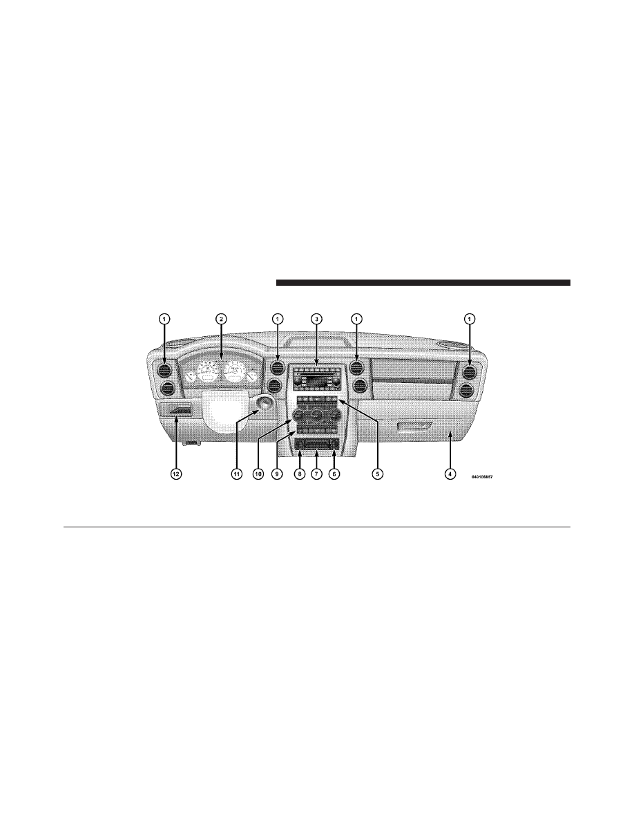
INSTRUMENT PANEL FEATURES
1 — Air Outlet
5 — Upper Switch Bank
9 — Lower Switch Bank
2 — Instrument Cluster
6 — Power Outlet/Cigar Lighter
10 — Climate Controls
3 — Radio
7 — Storage Bin
11 — Ignition Switch
4 — Glove Compartment
8 — Power Outlet
12 — Storage Bin
158
UNDERSTANDING YOUR INSTRUMENT PANEL
INSTRUMENT CLUSTER
4
UNDERSTANDING YOUR INSTRUMENT PANEL
159

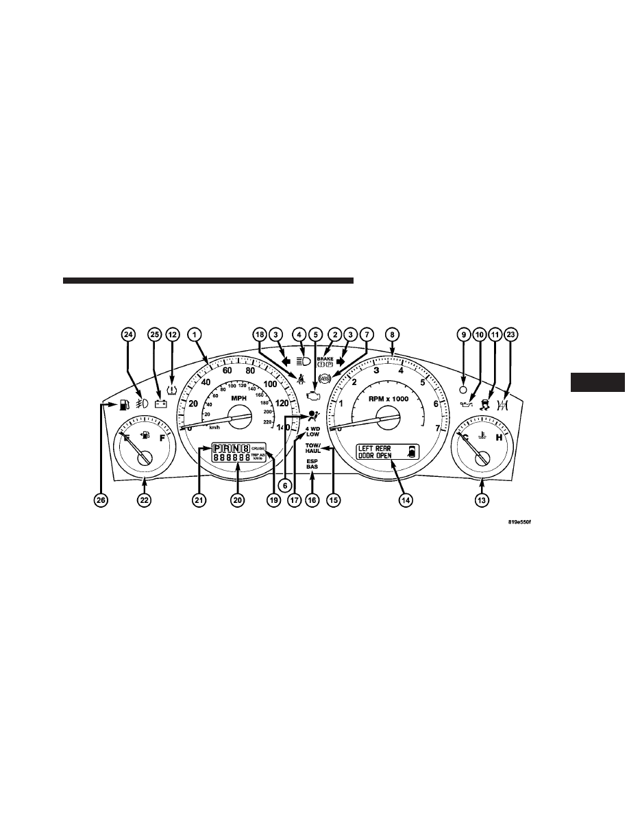
INSTRUMENT CLUSTER DESCRIPTION
1. Speedometer
Indicates vehicle speed.
2. Brake Warning Light
This light monitors various brake functions,
including brake fluid level and parking brake
application. If the brake light turns on, it may
indicate that the parking brake is applied, that
the brake fluid level is low, or that there is a problem with
the anti-lock brake system reservoir.
If the light remains on when the parking brake has been
disengaged, and the fluid level is at the full mark on the
master cylinder reservoir, it indicates a possible brake
hydraulic system malfunction or that a problem with the
Brake Booster has been detected by the Anti-Lock Brake
System (ABS) / Electronic Stability Program (ESP) sys-
tem. In this case, the light will remain on until the
condition has been corrected. If the problem is related to
the brake booster, the ABS pump will run when applying
the brake and a brake pedal pulsation may be felt during
each stop.
The dual brake system provides a reserve braking capac-
ity in the event of a failure to a portion of the hydraulic
system. A leak in either half of the dual brake system is
indicated by the Brake Warning Light, which will turn on
when the brake fluid level in the master cylinder has
dropped below a specified level.
The light will remain on until the cause is corrected.
NOTE:
The light may flash momentarily during sharp
cornering maneuvers, which change fluid level condi-
tions. The vehicle should have service performed, and
the brake fluid level checked.
If brake failure is indicated, immediate repair is neces-
sary.
160
UNDERSTANDING YOUR INSTRUMENT PANEL
Нет комментариевНе стесняйтесь поделиться с нами вашим ценным мнением.
Текст